"Hello World" without an OS
This document will refer to the DOS version of this program and I recommend you read that first. You can find this article here. It also talks about the environment in use (FASM)
This is possible of course. A real operating system can get loaded too somehow, so we're using that same mechanism to load our hello world program. Since there is no OS this time, there is no DOS interrupt to call either, so we have to deal with whatever the BIOS gives us.
BIOS vs EFI
This document uses a BIOS system and not an EFI system. If you only have a new PC with an EFI system to test, enter the setup and enable the compatibility module. If the machine has an operating system already installed, it will likely refuse to start until you disable that setting again. The name of the setting is inconsistent across vendors, and not present in all EFI machines. It's often named "CSM" or "Legacy System" or similar.
The reason to use the BIOS is because it requires a lot less to work with, and it's well supported in various emulation software, which brings us to the next chapter.
QEMU
If there's one thing that's annoying, it's developing something for a real computer that requires a restart and creation of bootable media for every attempt.
It takes a lot of time to repeatedly copy your code over to the test machine, so using a virtual machine or emulator is better.
QEMU is easy to use for this purpose, primarily because we can tell it to run our program without having to create a virtual disk. To do so, it's easiest to create a script file in the directory that contains your hello world binary.
The contents on Windows can be as follows:
@ECHO OFF
PUSHD "%~dp0"
C:\Path\To\qemu-system-x86_64.exe -drive format=raw,file=hello.bin
POPD
This assumes your assembly file is named "hello.asm", which will result in "hello.bin" when assembled.
Don't forget that you have to exit QEMU before you can assemble the file, because QEMU will lock it while it's emulating.
Testing on real hardware
For real hardware you want to use floppy disks or usb drives. A tool like Rufus can write raw images to disk. Be aware that this will render other things of the disk inaccessible, and your operating system will no longer properly recognize it until you format it.
My test machine has a Pentium 2 and a floppy emulator, so I can essentially use a USB flash drive to simulate a floppy disk, even though USB boot itself is not supported.
⚠️ CAUTION ⚠️
When you try your program on a real machine, it's best to unplug all storage media except for the one with your program on it. When you do something wrong you may end up executing code you don't want to, and this can have various consequences, including overwriting real data.
Bootloader
When we did the DOS program, it could be up to 64kb,
but the binary file was only as long as needed.
A bootloader however must be exactly 512 bytes.
You can't just append zeros either,
because a basic bootloader contains 510 bytes for instructions,
followed by the hex bytes 55,AA.
If those two "magic" bytes are not present, your bootloader will not be accepted.
This layout also means that if we need more than 510 bytes for our instructions,
we need to write code that can load additional sectors from the media we're booting from.
FASM supports repeatedly generating bytes, so this task is not too difficult.
db 510 dup 0
db 55h,0AAh
These two instructions is all you need to make a file that is 512 bytes long, and ends in the required magic bytes.
The bad thing about this is that we need to change this constantly. If you add an assembly instruction anywhere in the code you find that it's now longer than 512 bytes.
FASM prints the size of the resulting binary in the success dialog, so we can just adjust the number as we like, but it's very annoying to do so.
Luckily for us, FASM also understands basic arithmetic, and we can do this for a dynamically extending zero section:
init:
    ;Assembly instructions go here

bootsect:
    ;Bootsector generator here
    db (init+510-bootsect) dup 0F4h
    db 55h,0AAh
This takes the label "init" which will be the first address of our binary, then adds 510 which results in the ending address of the zero stream, then subtracts the address of the "bootsect" label to get the absolute size. As we add code, the bootsect label address will get bigger while the other two numbers stay the same. Because the bootsect label is subtracted, the resulting number will get smaller as we add more code.
You may also notice that I replaced the zero byte in the first db
with 0F4h.
This is the hexadecimal code for the hlt instruction,
which stops the CPU until an interrupt is fired.
This is absolutely not necessary and you can leave it as a zero,
but it's a good idea to make the processor stop
if it ends up in the unused region of our bootloader.
Inspecting the binary
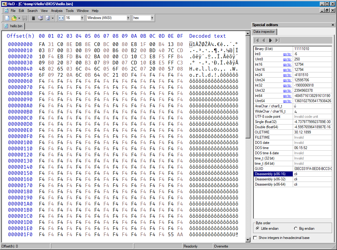
If you want to inspect the binary, you can use a hex editor. I use HxD on Windows. It's very fast, easy to use, can be opened from explorer context menu, can edit files of virtually any size, and it can show x86 disassembly.
You don't have to reload the file every time you assemble. The editor does so by itself every time you focus the window.
Initial commands
While DOS will set up your application in a deterministic way, the BIOS won't. Various CPU registers may be in an undefined state, so we should set them to zero. We should also set the stack pointer to a free memory location and ensure that we're not bothered by any interrupts.
init:
    ;Disable all interrupts that can be disabled
    cli
    ;Clear AX
    xor ax,ax
    ;Clearing DS and ES is only possible by copying a zeroed register
    mov ds,ax
    mov es,ax
    ;Set stack pointer to the beginning of our code
    mov sp,init
Disabling interrupts
This is generally a good idea if you don't want to handle any of them anyways. You can't disable all of them. NMI (Non Maskable Interrupt) cannot be disabled, but you seldom receive them anyways unless you really mess up.
Clearing registers
xor ax,ax seems like a weird way of clearing a register (setting it to zero),
but it's shorter in binary than mov ax,0.
Intel and other x86 manufacturers are aware of this
and the processor has optimized circuitery to handle this.
DS and ES cannot be cleared by xor, or mov with zero. This is because these registers have special meaning, and putting a constant into them, is seldom necessary. To clear them, you have to supply the zero in form of a register value. In our case we use AX, because we just cleared that.
About general purpose registers in x86
Note that throughout this document,
you encounter registers with an x at the end,
and registers with h and l at the end.
Registers can also start with e or r but we're not using those.
So the a (accumulator) register exists as rax,eax,ax,ah,al.
These function as follows:
rax: Accumulator that holds a 64 bit numbereax: Access to the lower 32 bits ofraxax: Access to the lower 16 bits ofeaxah: Access to the high 8 bits ofaxal: Access to the lower 8 bits ofax
This means that if we want to set ah and al to some value,
we can set them individually,
or use ax to set them simultaneously.
This can be visualized using a table:
| "a,b,c,d" Registers | |||||||
|---|---|---|---|---|---|---|---|
| RAX (64 bits) | |||||||
| N/A | EAX (32 bits) | ||||||
| N/A | AX (16 bits) | ||||||
| N/A | AH (8 bits) | AL (8 bits) | |||||
Other registers are set up in a similar way, but may use a different naming scheme.
The stack
The stack is memory that is used to store certain values temporarily.
It's special in how you access it. You can push stuff onto the stack
and pop it off the stack again.
Values are returned in the reverse order of how they were put on the stack,
so "push 1, push 2, push 3" will put 1, then 2, then 3 on the stack.
"pop, pop, pop" will get 3, then 2, then 1 off the stack.
The system itself also uses it, so you have to be careful to always leave it in a clean state.
The sp (stack pointer) CPU register holds the address of the current stack location.
When you push something onto the stack,
it will decrement the value of SP first,
then store your value at the location where SP points to now.
pop will copy the contents of the location where SP points to into your register,
then increments the value of SP.
This means the stack grows downwards towards address zero as you put stuff in it.
I shortly mentioned the problem that this can overwrite other memory
when I explained the DOS .COM layout.
By setting the stack to the start of our code, we can essentially make it grow away downwards from our code.
Function calls
The stack is also used for function calls. Our DOS assembly code just runs top to bottom once and then exits, but this gets messy for long code segments, it also means if you want to do the same thing in different locations, you have to copy and paste that code to all those locations.
You can use call and ret to implement reusable instructions.
call label puts the address of the next instruction onto the stack,
then jumps to the specified label.
ret will get a value from the stack and then jumps to that address.
This can cause problems when you don't carefully manage the stack:
call test
hlt

test:
    push 1337
    ret
This code will call the test function,
but because this function puts a value onto the stack,
ret will read this value from the stack instead of the address that was put there by call.
Note that we're not using the stack ourselves directly in the "hello world" code,
but it's still important to know how it functions for when you're eventually going to use it.
Printing string with the BIOS
Similar to the DOS int 21h services,
the BIOS offers a few functions too.
One of them is used to print an individual character.
That one will work on any system.
Another function can be used to print an entire string, and even set the color. This one we're going to use. It needs an EGA or newer card, which means it's going to run on pretty much everything.
Getting the screen into a defined state
The state of the screen is not entirely given when your bootloader runs. Some computers will clear it before, some others wont. We deal with clearing it later.
Print string code
The BIOS function to print a string is int 10h
with ah set to 13h.
Details can be found here.
The function wants to access many registers for various purposes:
- ah: The print function
- al: Two bits.
XYb: X=String contains color info; Y=Update cursor after printing - bh: Page number. In text mode, multiple pages are present. Page 0 is active by default.
- bl: Color of the string. Ignored if the string color bit in AL is set
- cx: Length of string in bytes
- dh: Row where to print
- dl: Column where to print
- bp: Address of the string
About pages
Computers support multiple pages, and you can switch between them. This allows you to print text in the background and then render everything at once, or use a page as an easy way to restore a snapshot. We will use page 0 for all commands that need a page.
Explanation of the values in use
We set AL to 1b so it updates the cursor.
BH is set to zero, and BL to 7. The 7 means gray text on black background.
CX is set to 13 because that's the length of "Hello, World!".
DH and DL are both set to zero via DX. This prints in the top left corner.
Code so far:
init:
    cli
    xor ax,ax
    mov ds,ax
    mov es,ax
    mov sp,init

print:
    mov ah,13h
    mov al,01b
    mov bh,0
    mov bl,7
    mov cx,13
    mov dh,0
    mov dl,0
    mov bp,text
    int 10h

done:
    hlt
    jmp done

text:
    db "Hello, World!"

bootsect:
    db (init+510-bootsect) dup 0F4h
    db 55h,0AAh
Now you can try to run this in QEMU and it will print something in the top left corner,
but it's not Hello, World!. It prints ■ ≡çΘ ≡s╘ ≡s╘ or some similar garbage.
But at least the color matches, right?
Of course you realize that you forgot the org 100h but that won't work either.
Address 100h was for DOS, but we're not running DOS. We're not running anything.
Our string has to be somewhere in memory. We could essentially start at zero, and go up until we find the string, or we can just consult the documentation. The documentation of x86 memory layout in particular.
The layout is as follows (Start and End in hexadecimal, table up to the point we care):
| Start | End | Type | Description |
|---|---|---|---|
| 00000000 | 000003FF | IVT | Unusable as storage |
| 00000400 | 000004FF | BDA | Unusable as storage |
| 00000500 | 00007BFF | Free | Free to use |
| 00007C00 | 00007DFF | Boot | 512 byte bootsector |
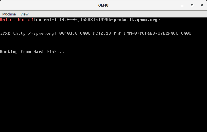
According to this, we can try org 7c00h and voilà:
Hello World in QEMU.
For readability, I changed the color to red.
The text is just in the top left corner, which kinda sucks. To fix this, we can read the cursor position using BIOS.
This is remarkably easy:
mov ah,03h ;Get cursor position
mov bx,0   ;Page
int 10h
The cursor position will now be in DH and DL register. This is very convenient, because the string print function wants them in those registers too. It's as if the person that made this was smart, fantastic.
So you put this code directly after the "print" label, and remove the "mov dh,0" and "mov dl,0" lines from the string print function.
Now it's time to make this fancy.
The string print function has the option to interleave color codes with characters in the string.
The string db "AB" needs to be rewritten as db 'A',ColorOfA,'B',ColorOfB.
The string can be up to 64 kilobytes in theory,
in practice, we're constrained by the 512 byte bootsector
if we don't want to add code to load stuff from disk.
Color table
We have 16 colors available for foreground and background. In reality, it's 8 colors, once dim and once bright. Using hexadecimal, this is quite comfortable to use because it fills exactly one hexadecimal digit for each of the two colors. If your color is a single hexadecimal digit, it sets the text color to that value, and the background to black. If it's two digits, the leftmost digit is background, the rightmost digit the text color.
| Default EGA 16-Color Palette |
||
|---|---|---|
| Color | Name | RGB |
| 0 | black | #000000 |
| 1 | blue | #0000AA |
| 2 | green | #00AA00 |
| 3 | cyan | #00AAAA |
| 4 | red | #AA0000 |
| 5 | magenta | #AA00AA |
| 6 | yellow / brown | #AA5500 |
| 7 | white / light gray | #AAAAAA |
| 8 | dark gray / bright black | #555555 |
| 9 | bright blue | #5555FF |
| A | bright green | #55FF55 |
| B | bright cyan | #55FFFF |
| C | bright red | #FF5555 |
| D | bright magenta | #FF55FF |
| E | bright yellow | #FFFF55 |
| F | bright white | #FFFFFF |
Note: "Yellow (6)" is rendered as brown or orange. "White (7)" is the default foreground color. Grey (8) is a bit darker than that, and "Bright White (F)" is true white.
With this information we can create a rainbow string.
Example (split on two lines for readability):
text:
    db 'H',2,'e',3,'l',4 ,'l',5 ,'o',6 ,',',7 ,' ',0
    db 'W',8,'o',9,'r',10,'l',11,'d',12,'!',13
Note that you have to follow every character with a color code, even characters that are not visible, such as a space.
At this point, it will print Hello, World! in rainbow coloring directly below any BIOS messages still on display.
Additional tasks
This chapter contains additional things you can do to make this look nicer
Clear screen
Below is the code for a clear screen function:
cls:
    mov ah,09h   ;Write character
    mov al,' '   ;Character to write
    mov bh,0     ;Page
    mov bl,7     ;Color (see above)
    mov cx,80*25 ;Repetitions
    int 10h
    ret
You can call it from anywhere using call cls.
This will essentially tell the BIOS to print a space character 25*80=2000 times.
This is the standard resolution of text mode:
80 characters wide, 25 rows tall.
Set cursor to (0,0)
Clearing the screen will not reset the cursor back to the top left. This has to be done manually. Setting the cursor to the top left corner is quite easy:
set0:
    mov ah,02h
    mov dx,0
    int 10h
    ret
Now you can modify the clear screen function to call set0 first and last. Calling it first makes sure we really overwrite everything, calling it after overwriting restores the cursor back to the top left.
If done properly, the screen will now exclusively show the colored "Hello, World!" string in the top left corner.
If you want to center it to the screen, just set the cursor to the appropriate position. The screen is 25 rows tall and 80 characters wide, so setting DH and DL in your print string function will do the trick:
mov dh,25/2
mov dl,80/2-(13/2)
Notes:
The math here will be performed by the assembler once, and the result hardcoded in the binary. You can also just calculate it yourself (dh=12, dl=34), but leaving the calculation in, will explain the numbers better.
Integer math always cuts off any decimals.
This means that 9/2/5 is zero because 9/2=4.5, which is cut off to just 4,
and 4/5=0.8 which again, has the decimals cut off, so the result is zero.
The processor will behave in the same way unless you use floating point math commands.
Final code
Below is the final code to print a rainbow "Hello, World!" on the screen center. It also shows how you can use constants to make your life easier. Constants are not part of the final binary, they're for you so you can read and understand your own code easier. You can see them as a "find and replace" thing. Them being all uppercase is not necessary either, but commonly done this way.
;BIOS Functions
SET_CURSOR_POS     = 2h
PRINT_CHARACTER    = 9h
PRINT_STRING       = 13h

;BIOS interrupt
BIOS_CALL          = 10h

;Function flags
FLAG_USE_COLOR     = 10b
FLAG_UPDATE_CUSROR = 1b

;Values for the screen
MAIN_SCREEN_PAGE   = 0
ROWS               = 25
COLS               = 80

;Length of "Hello, World!"
STRLEN             = 13

;Values for assembling the binary as x86 bootsector
BOOTSECT_SIZE      = 512
BOOTSECT_OFFSET    = 7c00h

;This is where BIOS loads our code in memory
org BOOTSECT_OFFSET

;We set up some registers before we can call BIOS functions
init:
    cli        ;Disable all maskable interrupts. We don't need them
    xor ax,ax  ;Clear the AX register. This is shorter than "mov ax,0"
    mov ds,ax  ;Clear DS and ES register. You can't directly do "mov ds,0" or "mov es,0"
    mov es,ax
    ;Set stack pointer just below the address of our entry point.
    ;The memory area below our bootloader is free for us to use down to 0x500.
    mov sp,init

    call cls   ;Clear the screen

;This uses the BIOS print string function to output our string with colors
print:
    mov ah,PRINT_STRING
    mov al,(FLAG_USE_COLOR or FLAG_UPDATE_CUSROR)
    mov bh,MAIN_SCREEN_PAGE
    mov bl,0                  ;Ignored
    mov cx,STRLEN
    mov dh,ROWS/2             ;Center vertically
    mov dl,COLS/2-(STRLEN/2)  ;Center horizontally
    mov bp,text               ;String address
    int BIOS_CALL

;End execution of our bootloader
done:
    hlt       ;Halt processor
    jmp done  ;Go back to halting if the processor was awakened by an interrupt

;Reset cursor to top left
set0:
    mov ah,SET_CURSOR_POS
    mov dx,0  ;Sets DH and DL to 0 simultaneously
    int BIOS_CALL
    ret

;Clear the screen by writing 80*25 spaces to it
cls:
    call set0
    mov ah,PRINT_CHARACTER
    mov al,' '
    mov bh,0         ;Page
    mov bl,7         ;Color
    mov cx,ROWS*COLS ;Screen size
    int BIOS_CALL
    call set0
    ret

;String to print. This is alternating between character and attributes.
;The character comes first, then the color of that character.
;This repeats for as many characters you want to print.
text:
    db 'H',2,'e',3,'l',4,'l',5,'o',6,',',7,' ',0,'W',8,'o',9,'r',10,'l',11,'d',12,'!',13

;Add magic number to mark this as bootable
bootsect:
    ;Write "hlt" instructions until binary is 510 bytes
    ;The formula subtracts space already in use by the code.
    ;It also takes the "org" at the beginning into account.
    db (init+(BOOTSECT_SIZE-2)-bootsect) dup 0F4h
    ;Write 55,AA to mark as bootable and be exactly 512 bytes.
    db 55h,0AAh
And yes, it does work on real hardware too. Tested on an Intel Pentium II using a floppy disk.
Real mode vs virtual mode (aka. "unreal mode")
This assembly program works in real mode, which is the 16 bit mode that x86 processors start up in. Usually you try to leave this mode as soon as possible to unlock most features of your processor.
the problem with this is that you cannot access most BIOS interrupts in this mode.
You have two ways of dealing with this.
One is to temporarily revert back to real mode,
the other is to not use the BIOS interrupt.
The BIOS interrupt to print strings is nothing more than a glorified memory copy routine.
The text display is actually memory mapped at address 0xB8000 and you can write to it directly
by simply writing beginning at that location.
A character consists of two bytes. The first byte is the character itself,
the second byte is the attribute,
which in standard display mode consists entirely of colors
(see "Color table") chapter above.
The default color is 7, which is the standard grey on black.
This means 0xB8000 is the character in the top left corner,
0xB8001 is the color of the character,
0xB8002 is the next character, 0xB8003 is the color of that character, etc.
Clearing the screen
Clearing the screen without the BIOS means we just write 2000 spaces into the screen area. (2000 = 80 width * 25 lines)
Writing text
Writing our text is done in a similar fashion to the screen clearing. We write character by character until we reach the end of the text.
Code
org 7c00h

;Address of video memory
VIDEO_START=0xB8000

;80 columns, 25 rows, 2 bytes per char
VIDEO_LENGTH=80*25*2

;End of video memory (first address of next memory block)
VIDEO_END=VIDEO_START+VIDEO_LENGTH

init:
    cli
    mov eax,VIDEO_END ;Make eax point to after the video memory
    mov bl,' '        ;The space character is used to clear the screen
    mov bp,text       ;Address of string (used in the printloop)

;Clear screen by writing spaces over the 80*25 field
space:
    sub eax,2           ;Subtracting 2 at a time to jump over the character attributes
    mov [eax], bl
    cmp eax,VIDEO_START ;Repeat until at video start
    jne space

;Value in EAX is now VIDEO_START because we went backwards
;We could go forwards as well, but since we want to write text,
;going backwards means we save a "mov eax,VIDEO_START" instruction

printloop:
    mov bl,[bp]     ;Copy character from our text to video memory
    mov [eax], bl   ;You cannot do "mov [mem],[mem]" directly,
                    ;Instead you need to do memory --> register --> memory

    add eax,2       ;Adding 2 instead of 1 skips over the attribute
    inc bp          ;Point to next character of our string

    cmp byte [bp],0 ;Check if memory is a zero and
    jnz printloop   ;continue if it's not

;Turn our space heater off
done:
    hlt
    jmp done

;String that is printed
text:
    db "Hello, World!",0

;Write this binary as a boot sector
bootsect:
    db (init+510-bootsect) dup 0F4h
    db 55h,0AAh